
适用于移动平台的快速生成地形剖面线方法
作者简介:汪琦(1989-),男,浙江杭州人,硕士生,研究方向为移动GIS。E-mail: sevenmilan@163.com
收稿日期: 2015-03-09
要求修回日期: 2015-03-30
网络出版日期: 2015-07-08
基金资助
中央高校基本科研业务费专项资金资助(TD2014-02)
中国地质调查局地质调查工作项目“数字地质调查系统开发”(1212011120436)
An Algorithm for Rapidly Generating Terrain Section Line on Mobile Platform
Received date: 2015-03-09
Request revised date: 2015-03-30
Online published: 2015-07-08
Copyright
本文针对移动平台内外存储容量小,处理器相对较弱的特点,通过数字高程模型(DEM,包括不规则三角网和规则格网),提出一种适用于移动平台的等高线直接生成剖面线的方法。与其他2种数字高程模型的剖面线生成方法的对比表明,本方法计算简单、运算量小、操作方便、成果图精度适宜,非常适合用于移动GIS。另外,针对在等高线生成剖面线过程中,路线处于2条等高线之间(即与等高线没有交点),无法求得路线高程值的情况,提出了通过作路线上任意点的水平和垂直方向直线,求得该直线与最邻近等高线的交点,利用4个交点的高程值求出路线上该点的高程值的方法。通过该方法,求出足够多高程点,进而生成剖面线。将本文提出的移动平台快速生成地形剖面线算法,应用于区域地质调查,较好地解决了实际应用中遇到的问题,取得了良好的效果。
汪琦 , 陈飞翔 , 彭俊杰 . 适用于移动平台的快速生成地形剖面线方法[J]. 地球信息科学学报, 2015 , 17(7) : 830 -836 . DOI: 10.3724/SP.J.1047.2015.00830
This paper depicts a terrain section line generation method using the contour line. The method is adaptive to the relatively weak performance of mobile platform which has smaller internal and external storage capacity and lower computing ability of processor compared to a desktop platform. On the desktop platform, digital elevation model (DEM, including triangular irregular network and regular grid) is often used to generate terrain section line, which is also the basis of our proposed method. By comparing it with two other methods for generating terrain section line through digital elevation model, we found that the proposed method in this paper is much simpler and faster in calculation, more convenient in operation, and meanwhile has an appropriate accuracy in the result chart. It is quite suitable for mobile GIS use. In addition, this paper presents a solution for the case that a route is located between two contour lines. In other words, the route has no intersection with the closest contour lines while the traditional algorithm cannot figure out its elevation value. By making a horizontal straight line and a vertical straight line across a certain point on the route, the four intersections of the straight lines and the point's two nearest contour lines are obtained. Then, the elevation value of this point could be calculated using the four intersections' elevation values. With this method, enough elevation points could be obtained to generate the final terrain section line. It solves the problems encountered in the practical applications with a good result. In summary, the proposed method in this paper contains eight steps. Step1: thinning the measured route for reducing the amount of computation. Step2: finding out the intersection set of the thinned route and the contour lines, and then obtaining the elevation value for each intersection. Step3: checking whether the intersection set is empty. If yes, then execute step 4, if not, jump to step7. Step4: at a certain point, make a horizontal line and a vertical line across it for obtaining the intersections with the contour lines. Step5: obtaining the four intersections' elevation values and calculating the distances between the four intersection points and the certain point. Step6: calculating the elevation value of the certain point using a formula, and then use the same approach to obtain enough amount of points' elevation values. Step7: to ensure the final section line is smooth, more elevation points are acquired through interpolating to the existing elevation points. Step8: drawing the final terrain section line by sequentially connecting the elevation points. Finally, the proposed algorithm is applied in the production of regional geological survey, and achieves good results.
Key words: contour line; terrain section line; mobile GIS; DEM
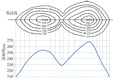
Fig. 1 The base line generates the section line图1 基线生成剖面线 |
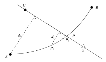
Fig. 2 The coordinates for the intersection point of a straight line and curve图2 直线与曲线交点坐标 |
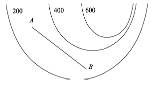
Fig. 3 The base line has no intersection with the contour line图3 基线与等高线无交点 |
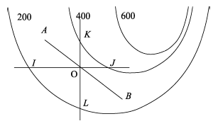
Fig. 4 Make horizontal and vertical lines across any point for their intersections with the adjacent contours图4 过点作直线求交点 |
Tab. 1 Comparison of section generation methods on PC表1 PC端剖面生成方法对比 |
| 指标 | 方法 | ||
|---|---|---|---|
| 规则格网 | 不规则三角网 | 本文算法 | |
| CPU占用率(%) | 70 | 80 | 20 |
| 内存占用率(%) | 50 | 60 | 20 |
| 完成时间(s) | 4 | 5 | 2 |
| 剖面精度(%) | 96 | 98 | 93 |
注:剖面精度结果为数字化生成图像与手工绘制图相似度 |
Tab. 2 Comparison of section generation methods on mobile device表2 移动端剖面生成方法对比 |
| 指标 | 方法 | ||
|---|---|---|---|
| 规则格网 | 不规则三角网 | 本文算法 | |
| CPU占用率(%) | >100 | >100 | 80 |
| 内存占用率(%) | >100 | >100 | 80 |
| 完成时间(s) | >3600 | >3600 | 15 |
| 剖面精度(%) | 96 | 98 | 93 |
注:剖面精度结果为数字化生成图像与手工绘制图相似度 |
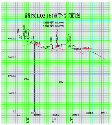
Fig. 5 Cross-sectional view图5 信手剖面图 |
The authors have declared that no competing interests exist.
| [1] |
|
| [2] |
|
| [3] |
|
| [4] |
|
| [5] |
|
| [6] |
|
| [7] |
|
| [8] |
|
| [9] |
|
| [10] |
|
| [11] |
|
| [12] |
|
| [13] |
|
| [14] |
|
| [15] |
|
| [16] |
|
| [17] |
|
| [18] |
|
| [19] |
|
| [20] |
|
| [21] |
|
| [22] |
|
| [23] |
|
| [24] |
|
| [25] |
|
| [26] |
|
| [27] |
|
/
| 〈 |
|
〉 |