
机载SAR干涉定标参数分离式解算方法研究
作者简介:申琳(1990-),女,硕士生,研究方向为InSAR及应用。E-mail: lshen90@foxmail.com
收稿日期: 2014-11-18
要求修回日期: 2015-04-30
网络出版日期: 2015-07-08
基金资助
国家自然科学基金项目(41171267)
Study on the Parameters-separated Solving Method of Airborne SAR Interferometric Calibration
Received date: 2014-11-18
Request revised date: 2015-04-30
Online published: 2015-07-08
Copyright
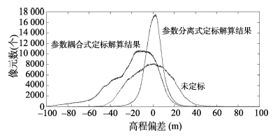
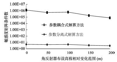
机载干涉合成孔径雷达(Interferometric Synthetic Aperture Radar,InSAR)是获取地面数字高程模型(Digital Elevation Model,DEM)的重要手段之一。InSAR系统参数误差会影响生成DEM的精度,利用干涉定标技术可以校正系统参数,补偿系统误差。目前,机载SAR干涉定标解算方法多采用天线基线长度、基线倾角,以及干涉相位偏置3个参数共同构建敏感度矩阵解算干涉定标参数偏差(参数耦合式解算方法)。由于机载InSAR系统对干涉相位偏置参数的敏感度较小,与基线长度、基线倾角的敏感度存在数量级差异,3个参数共同构建敏感度矩阵病态严重,易将微小的参数扰动传播扩大为较大的解向量误差,影响干涉定标精度,同时增大算法对干涉定标外场实验中角反射器布设高程的敏感度。本文提出一种机载SAR干涉定标参数分离式解算方法,在干涉定标解算过程中,对基线长度、基线倾角及干涉相位偏置3个参数进行分离,选取基线长度与基线倾角2个参数构建敏感度矩阵进行解算,对干涉相位偏置参数进行单独拟合解算,最终获得3个参数的综合定标结果。经机载双天线InSAR系统获取的真实数据验证,与参数耦合式解算方法相比,利用参数分离式解算方法构建得到的敏感度矩阵条件数由1.07E+06下降至5.02,系统参数定标后生成DEM与高精度参考DEM的平均高程偏差由14.98 m下降至6.51 m,干涉定标精度显著提高。另外,根据角反射器布设高程数值仿真模拟分析结果,与参数耦合式解算方法相比,参数分离式解算方法对角反射器布设高程变化的敏感度显著降低,对角反射器布设高程的普适性较高,且算法解算精度在角反射器布设高程起伏较小时不受明显影响,有助于减轻机载SAR干涉定标的野外工作强度。
申琳 , 曾琪明 , 焦健 . 机载SAR干涉定标参数分离式解算方法研究[J]. 地球信息科学学报, 2015 , 17(7) : 862 -870 . DOI: 10.3724/SP.J.1047.2015.00862
Airborne interferometric synthetic aperture radar (InSAR) is one of the key methods to generate digital elevation model (DEM). As the accuracy of DEM would be affected by errors of InSAR system parameters, it is necessary to correct system parameters and compensate system errors using interferometric calibration. Most of the solving methods for airborne InSAR calibration establish the sensitivity matrix with antenna baseline length, baseline obliquity and phase bias jointly to calibrate parameters’ errors, which can be referred as the parameters-coupled solving methods. Since the sensitivity of phase bias is much smaller than baseline length and baseline obliquity, it would easily cause the sensitivity matrix to be ill-conditioned when establishing the sensitivity matrix with the three parameters together. In this situation, errors of the solution vector could be amplified, which consequently affects the interferometric calibration accuracy, and increase the sensitivity of corner reflectors’ locating heights to calculations. This paper presents a parameters-separated solving method for airborne InSAR calibration by separating the baseline length, baseline obliquity and phase bias during the calibrating-solving process. The method establishes the sensitivity matrix with baseline length and baseline obliquity firstly, to calibrate these two parameters. Then, the phase bias was fitted individually, and afterwards we acquire the integrated calibration result of all three parameters. According to the validation result of real SAR data obtained by the dual antenna airborne InSAR system, the condition number of sensitivity matrix established by the parameters-separated solving method drops from 1.07E+06 to 5.02 comparing with the parameters-coupled solving method. Also, the average deviation of height, which accounts for the differences between DEM that generated by the calibrated airborne InSAR system and the reference DEM with high accuracy, drops from 14.98 m to 6.51 m. The interferometric calibration accuracy is improved significantly. Furthermore, the result of simulation analysis demonstrates that the locating height of corner reflectors has no distinctive impact on interferometric calibration accuracy when using the parameters-separated solving method. Therefore, the parameters-separated solving method has a higher adaptability regarding to different locating heights of corner reflectors, which can effectively reduce the intensity of field works for airborne SAR interferometric calibration.
Tab. 1 Sensitivity level of interferometric parameters表1 干涉参数敏感度量级 |
| 干涉参数 | 敏感度量级 |
|---|---|
| 基线长度 | 103 |
| 基线倾角 | 103 |
| 干涉相位偏置 | 101 |
| 斜距 | 10-1 |
| 多普勒中心频率 | 10-1 |
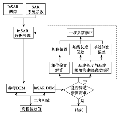
Fig. 1 Flowchart of airborne SAR interferometric calibration based on parameters-separated solving method图1 机载SAR干涉定标参数分离式解算方法流程图 |
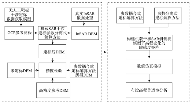
Fig. 2 Flowchart of experiment图2 实验流程图 |
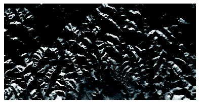
Fig. 3 Simulated airborne SAR image base on Range-Doppler (RD) model图3 基于距离-多普勒模型的模拟机载SAR图像 |
Tab. 2 Parameters of airborne SAR image表2 机载SAR图像主要参数 |
| 参数类型 | 参数值 |
|---|---|
| 波长(m) | 0.02 |
| 方位向分辨率(m) | 1 |
| 距离向分辨率(m) | 1 |
| 基线长度(m) | 1.215 |
| 基线倾角(rad) | 0.02618 |
| 波束中心与地面夹角(°) | 45.8 |
| 相对飞行高度(m) | 3500 |
| 工作模式Q | 1 |
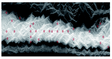
Fig. 4 Distribution of GCP on airborne SAR image图4 GCP在机载SAR图像上的分布 |
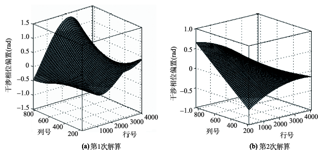
Fig. 5 Calculation of interferometric phase bias图5 干涉相位偏置解算 |
Tab.3 Iterative process and results of calibration表3 定标迭代解算过程及结果 |
| 干涉相位偏置(rad) | 基线长度(m) | 基线倾角(°) | 绝对高程差值众数(m) | |
|---|---|---|---|---|
| 未定标 | 0 | 1.2150 | 0.02618 | 3.176 |
| 第1次迭代解算 | +1.1876 | +0.0617 | +0.00199 | 1.117 |
| 第2次迭代解算 | +0.3173 | -0.0010 | +0.00060 | 0.513 |
| 最终定标结果 | 1.5049 | 1.2757 | 0.02877 |
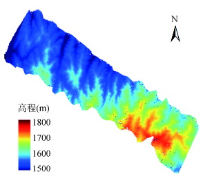
Fig. 6 Geocoded DEM using InSAR data after calibration图6 定标后经InSAR数据处理获得的DEM |
Tab. 4 Numerical statistics on height deviation表4 高程偏差数值统计 |
| 高程偏差范围(m) | 绝对偏差平均值(m) | 绝对偏差标准差(m) | |||
|---|---|---|---|---|---|
| ±2 | ±5 | ±10 | |||
| 未定标 | 7.53% | 18.44% | 34.49% | 21.36 | 18.64 |
| 参数耦合式解算定标 | 8.08% | 19.99% | 38.93% | 14.98 | 10.81 |
| 参数分离式解算定标 | 20.73% | 49.28% | 79.90% | 6.51 | 5.85 |
Fig. 7 Graph of height deviation curves图7 高程偏差曲线图 |
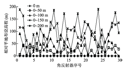
Fig. 8 Relative variations on the locating heights of corner reflectors图8 角反射器布设高程相对变化 |
Fig. 9 Variation of matrix condition number图9 矩阵条件数变化结果 |
The authors have declared that no competing interests exist.
| [1] |
|
| [2] |
|
| [3] |
|
| [4] |
|
| [5] |
|
| [6] |
|
| [7] |
|
| [8] |
|
| [9] |
|
| [10] |
|
| [11] |
|
| [12] |
|
| [13] |
|
| [14] |
|
| [15] |
|
| [16] |
|
| [17] |
|
| [18] |
|
| [19] |
|
| [20] |
|
| [21] |
|
/
| 〈 |
|
〉 |