
基于中轴变换算法的室内外一体化导航路网自动生成方法
作者简介: 武恩超(1990-),男,山东德州人,硕士生,研究方向为地理信息服务。E-mail: 153452679@qq.com
收稿日期: 2017-12-03
要求修回日期: 2018-03-03
网络出版日期: 2018-06-20
基金资助
国家重点研发计划(2016YFB0502104)
国家自然科学基金面上项目(41771436)
福建省科技创新平台建设项目(2015H2001)
Automatic Generation Method of Indoor and Outdoor Integrated Navigation Network Based on Medial Axis Transform Algorithm
Received date: 2017-12-03
Request revised date: 2018-03-03
Online published: 2018-06-20
Supported by
National Key Research and Development Program of China, No.2016YFB0502104
National Natural Science Foundation of China, No.41771436
Fujian Provincial Science and Technology Innovation Platform Construction Project, China, No.2015H2001
Copyright
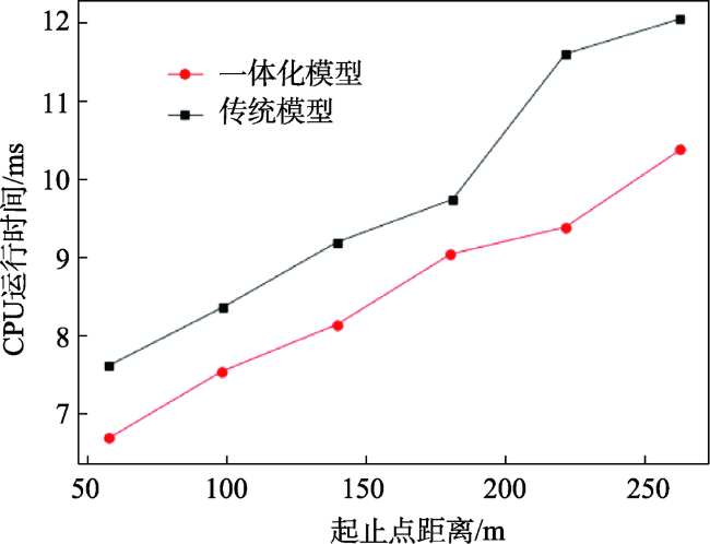
室内外一体化导航路网的快速生成与更新对面向行人的跨场景导航具有重要意义。当前研究主要关注单一场景下的导航路网构建,对于跨室内外场景的导航路网自动生成研究较少。本文基于对偶图思想与二维平面多边形中轴变换(Medial Axis Transform)算法,提出一种室内外一体化导航路网自动生成方法,并以某建筑CAD平面图及周边路网环境为基础数据进行了实例研究。结果表明:该方法能够根据原始数据的几何、拓扑、语义信息自动构建导航路网,并支持室内外跨场景的最短路径查询,在最短路径查询效率上较传统分场景寻路模型整体提升10.18%;相较单一场景下的导航路网,一体化导航路网可结合语义信息将室内及室外导航路网有机统一起来,解决跨场景寻求最优路径的问题,为最优路径规划的相关研究提供了新的思路。
武恩超 , 张恒才 , 吴升 . 基于中轴变换算法的室内外一体化导航路网自动生成方法[J]. 地球信息科学学报, 2018 , 20(6) : 730 -737 . DOI: 10.12082/dqxxkx.2018.170582
The rapid generation and updating of indoor and outdoor integrated navigation network are of great significance for pedestrian-oriented cross-scene navigation. The current researches mainly focus on the establishment of the navigation network in a single scene, and few researches on the automatic generation of the navigation network across the indoor and outdoor scenes. In this paper, a method for automatic generation of indoor and outdoor integrated navigation network is proposed based on Dual Graph and Medial Axis Transform algorithm, then a case study was carried out based on the data of a building's CAD plan and it's surrounding road network. The results show that this method can automatically build the navigation network according to the geometry, topology and semantic information of the original data and support the shortest path query of indoor and outdoor cross-scene. Compared with traditional sub-scene, the overall efficiency of the proposed routing algorithm has been improved by 10.18%; the integrated navigation network can combine the indoor navigation network with the outdoor navigation network reasonably through the semantic information. Compared with the navigation network under single scene, this method could solve the problem of finding optimal path across scenes, and provide a new idea for the research of first-best path planning.
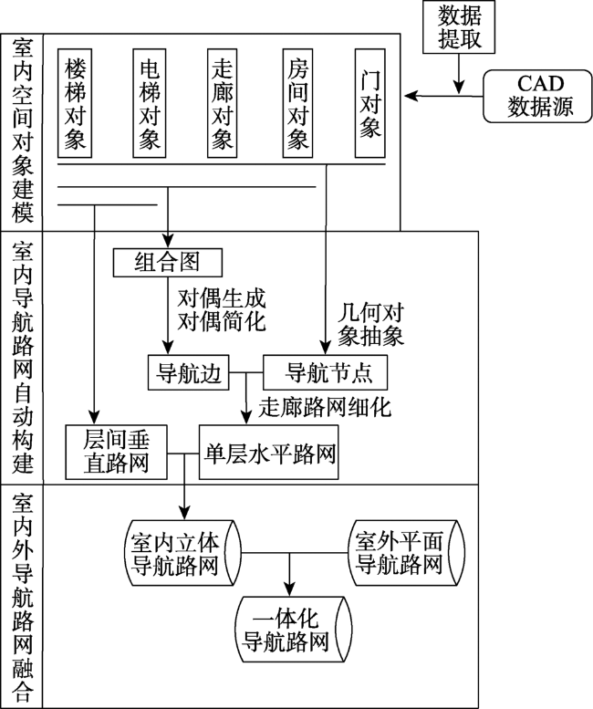
Fig. 1 Flowchart of indoor-outdoor integrated navigation network construction图1 室内外一体化导航路网构建流程图 |
Tab. 1 Construction of indoor navigation nodes表1 室内导航节点构建 |
| 导航节点类型 | 图标 | 属性 |
|---|---|---|
| 房间门 |  | {坐标,门号,方向,时空限制,备注} |
| 建筑物出入口 |  | {坐标,方向,时空限制,备注} |
| 电梯出入口 |  | {坐标,楼层号,电梯号} |
| 楼梯出入口 |  | {坐标,楼层号,楼梯号} |
| 房间节点 |  | {坐标,房间号,功能,说明} |
| 转向点 |  | {坐标} |
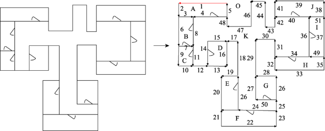
Fig. 2 Indoor spaces and embedded graphs图2 室内空间及其嵌入图表示 |
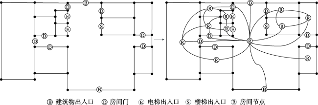
Fig. 3 Dual graph generation图3 对偶图生成 |
Fig. 4 The sketch map of navigation图4 导航示意图 |
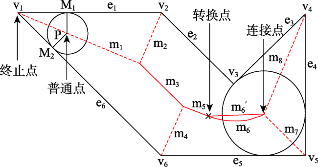
Fig. 5 The sketch map of medial axis transform in planar polygon R图5 平面多边形R中轴线示意图 |
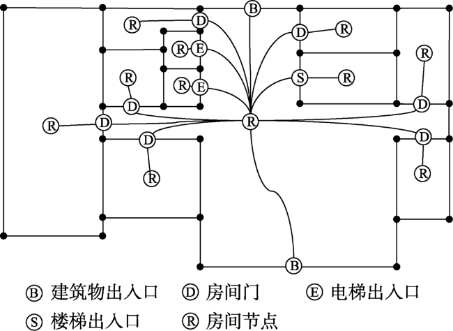
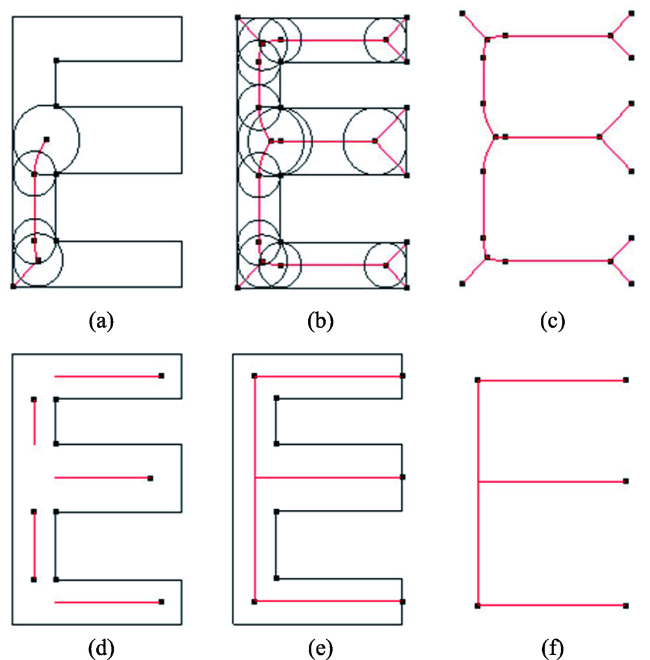
Fig. 6 Network extraction of complex corridor图6 复杂走廊路网提取 |
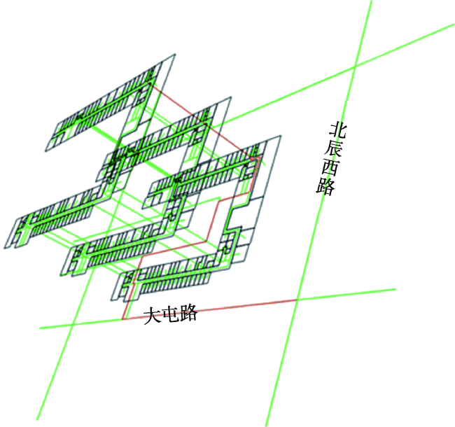
Fig. 7 Indoor and outdoor integrated navigation network and route query图7 室内外一体化导航路网及路径查询 |
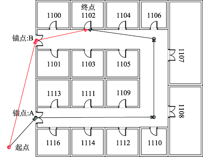
Fig. 8 Schematic diagram of optimal path inspection图8 最优路径检查示意图 |
Fig. 9 Comparison of efficiency of path planning图9 路径规划效率对比 |
The authors have declared that no competing interests exist.
| [1] |
[
|
| [2] |
[
|
| [3] |
|
| [4] |
[
|
| [5] |
|
| [6] |
|
| [7] |
|
| [8] |
|
| [9] |
|
| [10] |
|
| [11] |
|
| [12] |
|
| [13] |
|
| [14] |
|
| [15] |
|
| [16] |
|
| [17] |
|
| [18] |
|
| [19] |
[
|
| [20] |
|
| [21] |
|
| [22] |
[
|
| [23] |
|
| [24] |
|
/
| 〈 |
|
〉 |