
基于无人飞行平台的小型Ka波段合成孔径 雷达系统研制
作者简介:张 琦(1977-),男,四川绵阳人,博士,研究方向为信号与信息处理。E-mail: zhangq-7@126.com
收稿日期: 2018-09-10
要求修回日期: 2019-03-18
网络出版日期: 2019-04-24
基金资助
国家自然科学基金项目(61471340)
国家重点研发计划项目(2017YFB0503001)
Development of Ka-band Miniature Synthetic Aperture Radar based on UAV
Received date: 2018-09-10
Request revised date: 2019-03-18
Online published: 2019-04-24
Supported by
National Natural Science Foundation of China, No.61471340
National Key Research and Development Program of China, No.2017YFB0503001
Copyright
无人飞行平台具有滞空时间长、使用维护方便等优点,在军事侦查打击、国土资源普查、灾害监测等领域的应用日益广泛。合成孔径雷达是一种二维成像雷达,能够得到类似光学图片的雷达图像,具有全天候、高分辨率、宽检测范围等优点,是无人飞行平台的重要载荷之一。然而,受限于无人飞行平台相对较小的空间与负载能力,雷达载荷必须向小型、轻量以及低功耗等方面发展。Ka波段电磁波信号具有波长短、带宽大、关键微波器件的体积小等特点,适合应用于高分辨率微小型雷达载荷。2015年中国科学院电子学研究所面向中小型无人飞行平台,开展了研制的小型高分辨率Ka波段合成孔径雷达工作,并通过试飞验证了雷达性能。本文研究了Ka波段SAR雷达系统各项关键技术,介绍了雷达系统及关键模块设计方案、雷达各工作模式的参数设计和实时成像算法,展示了该雷达在轻型飞行平台上获得的高分辨率飞行图像,并对图像进行了指标分析。试验结果表明:该Ka波段雷达系统成像清晰,图像分辨率优于0.2 m,满足设计指标要求;实测雷达重量低于10 Kg,峰值功耗小于100 W,适用于轻小型无人飞行平台。
张琦 , 张雷 , 郭俊栋 , 胡建民 . 基于无人飞行平台的小型Ka波段合成孔径 雷达系统研制[J]. 地球信息科学学报, 2019 , 21(4) : 524 -531 . DOI: 10.12082/dqxxkx.2019.180453
Unmanned Aerial Vechicle (UAV) is widely used in military investigation and attack, land and resources survey, disaster monitoring and other fields because of its advantages such as long stay time and easy maintenance. Synthetic aperture radar (SAR) is a kind of two-dimensional imaging radar, which can obtain radar images similar to optical images. It has the advantages of all-weather, high resolution, wide detection range and so on. It is one of the important loads of UAV. However, due to the relatively small space and load capacity of UAV, radar load must be small volume, light weight and low power consumption. Ka-band electromagnetic wave signal has the characteristics of short wavelength, wide bandwidth and small size of key microwave devices. It is suitable for high resolution miniature radar load. In 2015, the Institute of Electronics, Chinese Academy of Sciences, developed a kind of high resolution Ka-band synthetic aperture radar for small or medium UAV. The performance of the SAR was verified by flight test. In this paper, the key technologies of Ka-band SAR radar system are studied. The design scheme of radar system and key modules, the parameter of each working mode and real-time imaging algorithm are introduced. The radar weight is less than 10 Kg, and the peak power consumption is less than 100 W. It is suitable for small or light UAV. The high-resolution flight images obtained by the radar on light flight platform are displayed, and the performance of the images are analyzed. The experimental results show that the Ka-band SAR system can generate clear radar image and meets the design requirements. For example, the image resolution is better than 0.2 m and the detection distance is greater than 10 km..The rapid progress of microwave device technology represented by solid-state high power amplifier is the foundation of the success of this project. The project is a new attempt to develop Ka-band SAR and apply it to UAV. It also makes a useful exploration for the further development of Ka-band synthetic aperture radar and has important application value. The development of small Ka-band synthetic aperture radar in the future depends on the maturity of semiconductor technology and the improvement of the performance of Ka-band microwave devices. On the other hand, it also depends on the research of new style SAR which has high duty cycle and pulse agility, which can improve the average power of radar and solve the problem of ambiguity of detection range.
Key words: UAV; SAR; Ka-band; millimeter wave; radar Image; chirp-scaling algorithm
Tab. 1 Frequency division of electromagnetic wave表1 常用的电磁波频带划分 |
| 波段符号 | 标称频率/GHz | 波长范围/mm | 波段符号 | 标称频率/GNz | 波长范围/mm |
|---|---|---|---|---|---|
| UHF | 0.30~1.12 | 1000.0~267.9 | Ka | 26.5~40.0 | 11.3~7.5 |
| L | 1.12~1.70 | 267.9~176.5 | Q | 30.0~50.0 | 10.0~6.0 |
| LS | 1.70~2.60 | 176.5~115.4 | U | 40.0~60.0 | 7.5~5.0 |
| S | 2.60~3.95 | 115.4~75.9 | M | 50.0~75.0 | 6.0~4.0 |
| C | 3.95~5.85 | 75.9~51.3 | E | 60.0~90.0 | 5.0~3.3 |
| XC | 5.85~8.20 | 51.3~36.6 | F | 90.0~140.0 | 3.3~2.1 |
| X | 8.20~12.4 | 36.6~24.2 | G | 140.0~220.0 | 2.1~1.4 |
| Ku | 12.4~18.0 | 24.2~16.7 | R | 220.0~325.0 | 1.4~0.9 |
| K | 18.0~26.5 | 16.7~11.3 |
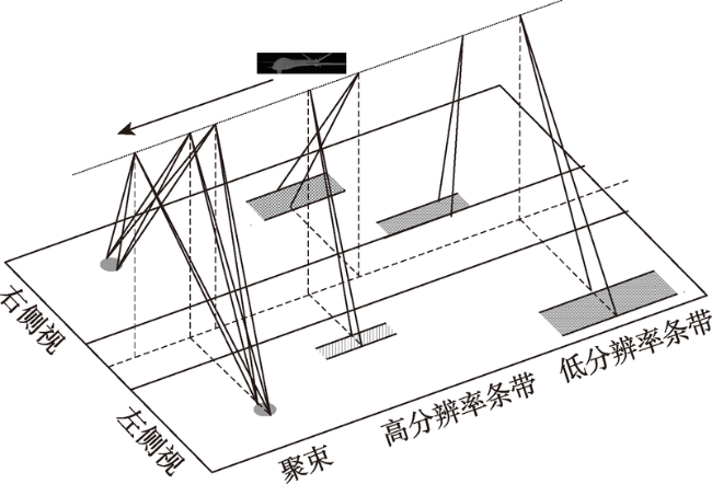
Fig. 1 Work for each mode of SAR图1 合成孔径雷达工作模式示意 |
Tab. 2 Performance for each mode of SAR表2 合成孔径雷达各模式设计指标 |
| ` | 极化 | 分辨率/m | 测绘带宽/km | 距离/km | 供电/V | 功耗/W | 重量/kg | |
|---|---|---|---|---|---|---|---|---|
| 垂直极化 | 聚束 | 0.3 | 0.5×0.5 | ≥ 10 | ||||
| Ka | 条带 | 0.3 | ≥2 | ≥ 8 | DC24~30 | <100 | <10 | |
| 1 | ≥4 | ≥ 10 | ||||||
Tab. 3 Pass attenuation rate of signal Transmission in different wavelength表3 不同波段信号的大气衰减比较[21] |
| X波段 | Ka波段 | W波段 | ||||||
|---|---|---|---|---|---|---|---|---|
| 晴天低空 | 中雨/(4 mm/h) | 晴天低空 | 中雨/(4 mm/h) | 晴天低空 | 中雨/(4 mm/h) | |||
| 衰减/(dB/km) | 0.02 | 0.30 | 0.24 | 1.00 | 0.80 | 3.00 | ||
Tab.4 Power Requirement for each mode of SAR表4 合成孔径雷达各模式功率需求 |
| 工作模式 | 分辨率/m | Rmax/km | Pav/W |
|---|---|---|---|
| 高分辨率条带 | 0.3 | 6 | 1.6 |
| 低分辨率条带 | 1.0 | 10 | 2 |
| 聚束模式 | 0.3 | 10 | 3 |
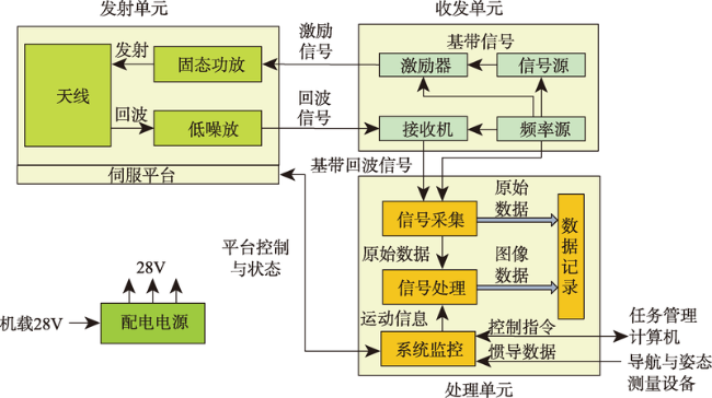
Fig. 2 Overview of SAR图2 合成孔径雷达组成 |
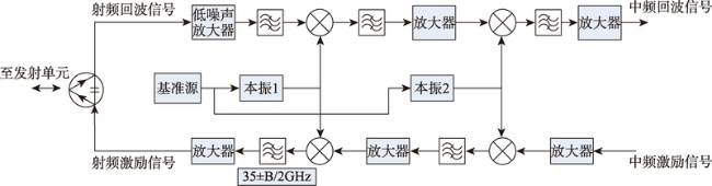
Fig.3 Design of Ka-band module in transceiver unit with Ka band图3 Ka波段收发单元内Ka波段模块设计 |
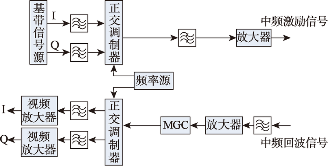
Fig. 4 Design of IF band module in transceiver unit with Ka band图4 Ka波段收发单元中频模块设计 |
Tab. 5 Cross-range resolution and the diameter of antenna in typical frequency bands表5 典型频段天线尺寸与理论方位向分辨率对比[22] |
| 频带范围/GHz | 天线口径/mm | 方位向分辨率/m |
|---|---|---|
| 10 | 3046 | 2.132 |
| 10.67 | 1827 | 1.279 |
| 35 | 870 | 0.609 |
| 94 | 324 | 0.227 |
| 140 | 218 | 0.152 |
| 220 | 138 | 0.097 |
注:波束宽度0.5°,展宽因子1.4。 |
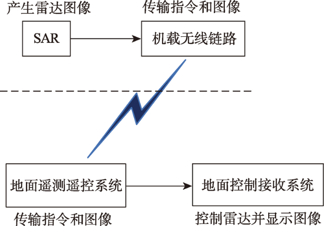
Fig. 5 Ground control of SAR in UAV图5 地面对无人飞行平台合成孔径雷达的遥控遥测 |
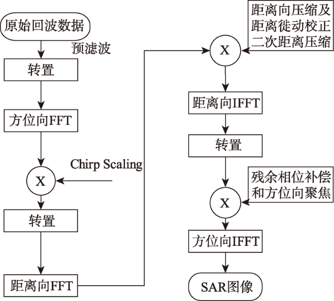
Fig. 6 Process of Image in SAR图6 合成孔径雷达实时图像处理流程 |
Tab. 6 Completion of Ka band SAR表6 Ka波段合成孔径雷达系统完成情况 |
| 外形(长×宽×高)/mm | 重量/kg | 功耗/W | |
|---|---|---|---|
| 天线 | 300×150×20 | 0.5 | |
| 功放单元 | 150×150×100 | 1.5 | 16 |
| 收发单元 | 300×250×250 | 5.2 | 35 |
| 处理单元 | 250×250×110 | 2.3 | 47 |
| 系统 | - | 9.5 | 98 |
Tab. 7 Performance of Ka band SAR when flying test表7 Ka波段合成孔径雷达系统飞行试验达到的性能指标 |
| 工作模式 | 飞行时作用距离/km | 测绘带宽/km | 图像分辨率/m |
|---|---|---|---|
| 高分辨率条带 | 8 | >4 | <0.2 |
| 低分辨率条带 | 12 | >6 | <0.5 |
| 聚束 | 10 | 0.5×1.5(方位×距离) | <0.2 |
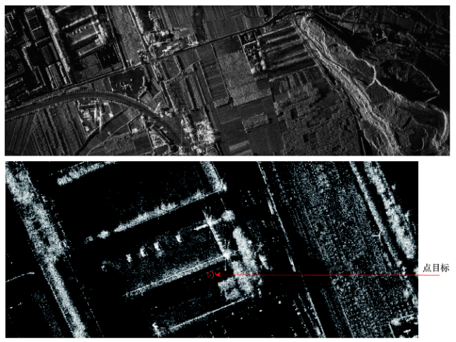
Fig.7 The high resolution image and its detail show图7 飞行成像试验得到的高分辨率图像及局部细节 |
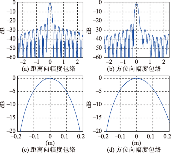
Fig. 8 Range and azimuth resolutions of point target in high resolution image of Ka band SAR图8 Ka波段合成孔径雷达高分辨率图像内点目标距离向和方位向的分辨率 |
The authors have declared that no competing interests exist.
| [1] |
[
|
| [2] |
[
|
| [3] |
[
|
| [4] |
[
|
| [5] |
[
|
| [6] |
[
|
| [7] |
|
| [8] |
[
|
| [9] |
[
|
| [10] |
[
|
| [11] |
[
|
| [12] |
[
|
| [13] |
[
|
| [14] |
[
|
| [15] |
[
|
| [16] |
[
|
| [17] |
[
|
| [18] |
[
|
| [19] |
|
| [20] |
[
|
| [21] |
[
|
| [22] |
[
|
| [23] |
[
|
/
| 〈 |
|
〉 |