武恩超 , 张恒才
, 张恒才
WU Enchao, ZHANG Hengcai
通讯作者:
收稿日期: 2017-12-3
修回日期: 2018-03-3
网络出版日期: 2018-06-20
版权声明: 2018 《地球信息科学学报》编辑部 《地球信息科学学报》编辑部 所有
基金资助:
作者简介:
作者简介: 武恩超(1990-),男,山东德州人,硕士生,研究方向为地理信息服务。E-mail: 153452679@qq.com
展开
摘要
室内外一体化导航路网的快速生成与更新对面向行人的跨场景导航具有重要意义。当前研究主要关注单一场景下的导航路网构建,对于跨室内外场景的导航路网自动生成研究较少。本文基于对偶图思想与二维平面多边形中轴变换(Medial Axis Transform)算法,提出一种室内外一体化导航路网自动生成方法,并以某建筑CAD平面图及周边路网环境为基础数据进行了实例研究。结果表明:该方法能够根据原始数据的几何、拓扑、语义信息自动构建导航路网,并支持室内外跨场景的最短路径查询,在最短路径查询效率上较传统分场景寻路模型整体提升10.18%;相较单一场景下的导航路网,一体化导航路网可结合语义信息将室内及室外导航路网有机统一起来,解决跨场景寻求最优路径的问题,为最优路径规划的相关研究提供了新的思路。
关键词:
Abstract
The rapid generation and updating of indoor and outdoor integrated navigation network are of great significance for pedestrian-oriented cross-scene navigation. The current researches mainly focus on the establishment of the navigation network in a single scene, and few researches on the automatic generation of the navigation network across the indoor and outdoor scenes. In this paper, a method for automatic generation of indoor and outdoor integrated navigation network is proposed based on Dual Graph and Medial Axis Transform algorithm, then a case study was carried out based on the data of a building's CAD plan and it's surrounding road network. The results show that this method can automatically build the navigation network according to the geometry, topology and semantic information of the original data and support the shortest path query of indoor and outdoor cross-scene. Compared with traditional sub-scene, the overall efficiency of the proposed routing algorithm has been improved by 10.18%; the integrated navigation network can combine the indoor navigation network with the outdoor navigation network reasonably through the semantic information. Compared with the navigation network under single scene, this method could solve the problem of finding optimal path across scenes, and provide a new idea for the research of first-best path planning.
Keywords:
随着以GPS、北斗为代表的室外定位技术及以WiFi、蓝牙、ZigBee等为代表的室内定位技术的日趋成熟,基于位置的服务与室内外一体化导航技术日益受到学界和产业界关注[1]。目前,室外导航路网数据大多以外业车采集、浮动车上传GPS轨迹数据及结合高分辨率遥感影像更新的方式采集,而室内导航路网主要由人工现场测量的方式生成。对于大型室内建筑(例如医院、机场)而言,用人工方式生成室内导航地图成本高昂且效率底下,而且室内建筑在其使用周期内持续不断的翻新改造进一步增加了维护导航路网时效性的难度,因此,自动构建导航路网,实时地规划行人导航路径,对于室内外一体化导航具有重要意义[2]。
导航路网自动生成的方法与空间结构密切相关[3],以往研究[5,6,7,8]已经指出室内和室外空间之间的主要结构差异。在路网结构方面,普通室外路网一般为2D结构,而室内路网多是具有三维立体特性[4]的复杂3D网络模型[6]。在室内导航路网自动生成研究方面,Stoffel等[9,10]提出富含语义信息的层次图模型以及基于平面图的层次图自动构建方法。Worboys等[8,11-13]指出室内空间结构与室内导航路网具有互为对偶的特性,Borovikov等[14]以三角形的对偶图[15]为基础,提出基于Delaunay三角形的室内导航路网自动构建方法。Lee等[11-12,16]同样采用几何构建方法,提出使用直接中轴转换方法用来生成几何网络模型。Choset等[17,18]定义了可视图的概念,由导航边连接两个室内空间中的可视节点。在一体化导航路网研究方面,朱欣焰等[19]基于建筑物室内场景语义层级结构,将室内对象的语法和语义整合,实现了全方位、多尺度和多粒度的室内外地上下一体化综合表达和可视化。
综上所述,目前研究主要聚焦于室内导航路网模型及构建方法,少数的室内外一体化导航路网研究偏重于建模与制图表达,有关一体化导航路网自动生成的研究较少。本文面向室内外无缝导航的路径规划需求,提出一种室内外一体化导航路网自动生成方法。首先,以建筑CAD平面图为基础,提取建筑平面图几何、语义信息,构建导航节点和导航边;然后,根据容差限制去除不含关键语义信息的冗余节点,从而简化整体导航路网结构;最后,通过建筑出入口(锚点)融合室内和室外导航路网,从而构建形成无需区分室内外场景的一体化导航路网。
室内外一体化导航路网是室内三维立体空间导航路网与室外二维平面导航路网的有机统一。一体化导航路网构建主要分为3个步骤:① 室内空间对象建模,原始CAD数据中带有室内空间的几何、语义信息,首先对其做分层处理,再借助FME(Feature Manipulate Engine)转换工具提取各室内空间对象的几何形状及其对应的语义信息进行室内空间对象的建模,主要的建模对象包括楼梯对象、电梯对象、房间对象、走廊对象和门对象;② 室内导航路网自动构建,根据之前步骤所建模型提取室内空间对象的几何信息并以组合图的方式表达室内平面空间,平面图取对偶,进行对偶简化后形成导航边对象,导航边与导航节点对象构成原始的导航示意图;建立走廊路网节点与走廊抽象节点的满射关系,细化走廊内部导航路网,完成室内导航路网的自动构建;③ 室内外导航路网融合,通过锚点将其与室外路网融合形成室内外一体化导航路网,整体流程如图1所示。
图1 室内外一体化导航路网构建流程图
Fig. 1 Flowchart of indoor-outdoor integrated navigation network construction
原始CAD数据带有精准几何信息和语义信息,但没有可用于计算的拓扑信息。因此首先将室内空间元素按其功能主要分成楼梯、电梯、走廊、房间和门五类空间对象,在数据提取过程中,针对不同的室内空间对象提取其几何与语义信息,建立几何对象与语义信息的对应关系,由语义信息判断该室内空间对象所属类别,通过这五类对象完成室内导航路网的自动构建。
室内导航路网构建主要包括导航节点的构建和导航边的构建。导航边代表可行走路径,导航节点代表决策点、地标或带有关键语义信息的转向点。室内导航路网与室外导航路网不同之处在于它是一种特殊的三维立体导航路网,其导航边兼具有水平方向的扩展和垂直方向的延伸。
2.2.1 室内导航节点构建
依据导航节点的类型、位置、语义等因素的组合,采用不同的方法构建导航节点。部分导航节点构建时需要参考空间对象的几何、拓扑关系,如转向节点,房间节点等;另外一部分导航节点构建时更关注空间对象的语义信息,如门节点,建筑出入口节点等。根据导航节点的语义划分主要定义6种节点类型,表1中给出了本文中用到的不同类型导航节点的图标、属性信息。
表1 室内导航节点构建
Tab. 1 Construction of indoor navigation nodes
| 导航节点类型 | 图标 | 属性 |
|---|---|---|
| 房间门 |  | {坐标,门号,方向,时空限制,备注} |
| 建筑物出入口 |  | {坐标,方向,时空限制,备注} |
| 电梯出入口 |  | {坐标,楼层号,电梯号} |
| 楼梯出入口 |  | {坐标,楼层号,楼梯号} |
| 房间节点 |  | {坐标,房间号,功能,说明} |
| 转向点 |  | {坐标} |
门:门节点是三维立体空间中的门对象在二维导航路网中的抽象表达。通过门节点,移动对象可实现在同一楼层中不同室内空间中的转移。
转向点:该类节点不对应现实室内空间中的具体对象,主要提供转向功能,移动对象可以根据实际情况决定在该类节点处直行,左转或右转,走廊转弯处的节点类型为转向节点。
建筑物出入口:任意一栋建筑至少具有一个出入口,通过该节点实现室内场景到室外场景的转移,该节点是室内外不同场景下导航路网建立连接的关键节点。
房间节点:房间节点是三维立体对象在零维空间的抽象,用一个没有大小只有坐标、属性的节点表示,该节点的出度、入度均为1。考虑到空间结构的相似性,楼梯空间、电梯空间的抽象方式与房间节点一样。
电梯出入口:类似门节点,利用电梯出入口节点,室内移动对象可以实现在垂直方向上的空间 转移。
楼梯出入口:除图标及部分属性不同,抽象方式同电梯出入口节点。
2.2.2 室内导航边构建
室内导航边构建的基本原则是在两相邻且相连通室内空间之间建立路网连接,其思想与平面对偶图生成一致。Edmonds[20]和Tutte[21]首先提出了组合图的概念,组合图提供了一种拓扑等价的表达嵌入图的方式,如图2所示。组合图
(1)有限集合
(2)
(3)
对给定的组合图
室内空间结构与室内导航路网具有互为对偶的特性,在组合图表达室内平面拓扑结构的基础之上,依据点—面对偶构建原则,将室内空间抽象为节点,对任意2个节点,基于组合图表达方式进行拓扑计算,若两室内空间彼此之间具有公共边界,则在两空间表示的节点之间建立边连接,如图3所示。
室内导航示意图是室内空间平面图的对偶简化,其简化过程是删减掉部分边:该边穿过的两室内空间的公共边界并不存在可供行人穿过的门对象。在实际情况中,如果2个相邻的房间A与B具有公共的墙体,但在该墙体上没有门对象,则不存在这样的从房间A到房间B的路径。对偶图简化后生成导航示意图,如图4所示。
在导航示意图中,走廊直接抽象为节点的表达方式只能在拓扑上表达移动对象的空间转移,并不具备为行人进行指路的能力,因此需要细化走廊内部导航节点。可以根据室内空间对象的属性及语义信息筛选出走廊对象,用NaviNodes表示走廊内部实际导航节点,CorridorPoint表示走廊抽象节点,则存在样的满射Corridor:NaviNodes→CorridorPoint。
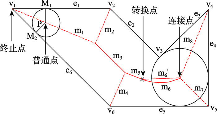
走廊路网的结构近似于走廊多边形的中轴 线[22,23,24],可用其中轴线来近似。令R表示一个平面多边形区域,
图5 平面多边形R中轴线示意图
Fig. 5 The sketch map of medial axis transform in planar polygon R
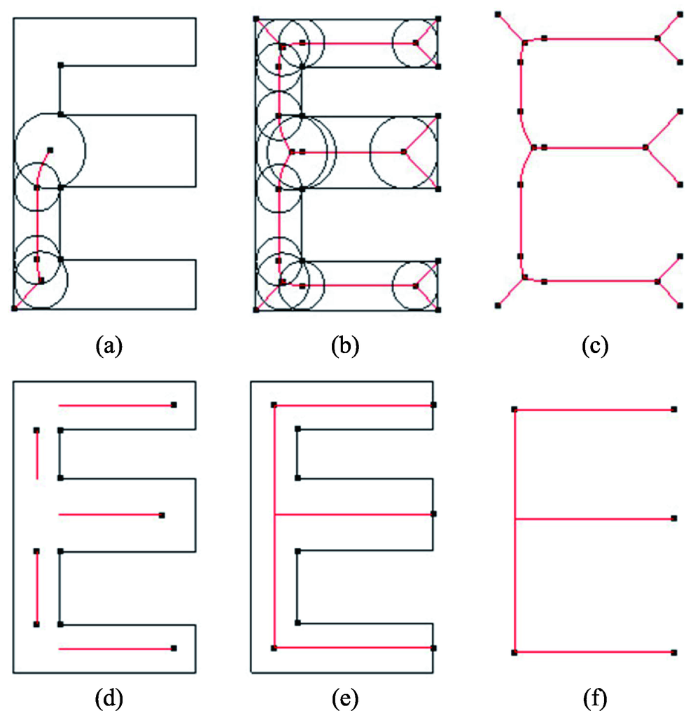
中轴线上每2个节点之间的线段或抛物线称为局部路线,局部路线的形状受主动边界元素类型的影响,主动边界元素是指在该局部路线生成过程中始终与平面多边形最大内切圆相正切的边界元素,由多边形全部的边和凹点组成,在图5所示的平面多边形R中,其主动边界元素集合为{ e1,e2,e3,e4,e5,e6,v3}。局部路线包括2类:① 由线-线确定的直线型局部路线;② 由线-凹点确定的抛物线形局部路线,在更复杂的多边形中还存在凹点-凹点确定的直线型局部路线。局部路线的生成过程本质是确定局部路线类型的起、止点和形状的过程,局部路线的形状主要由其管理者主动边界元素决定。局部路线管理者主动边界元素是主动边界元素的子集,每条局部路线都有自己的管理者主动边界元素集合。如图5中局部路线m1的管理者主动边界元素集合为{e1,e6},m1位于e1,e6夹角的内角平分线上。局部路线的起、止点主要由凸点的内角平分线与凹点边的垂线的交点及半径函数的关系确定。在图5中,以多边形的顶点(为凸点)v1作为中轴变换初始点,顶点v1的两边e1、e2作为主动边界元素决定局部线路m1的形状,顺时针到下一个凸点v2,v1及v2的角平分线的交点作为m1的终点,以此类推。图6(a)-(c)为某复杂走廊多边形中轴线提取过程。中轴线冗余线段去除及曲线段的“化曲为直”过程主要是将局部路线类型为抛物线或局部类型路线与角点相连的局部路线删除,对剩余类型为线段的局部路线任意两线段之间求交点,新的交点即为走廊路网新的节点。算法运行结果如图6(d)-(f)所示。
算法1 走廊内部导航路网生成算法
/* Parameters: Graph represented by combinatorial map */
Input(G(V,E))
Initialize remainMATPaths
InitializeFirstPath(d,g1,g2)
PushPath(d,g1,g2)
/*extract the medial axis paths*/
While not EmptyPath()do
PopPath(d,g1,g2)
/* calculate the key point of medial axis path */
TracePath(d,g1,g2,InterferenceList)
If not EndDisc(d) then
/* calculate the next line segment */
InitializeNewPaths(d,g1,g2,InterferenceList,NewPathList)
For path in newPathList do
PushPath(d,g1,g2)
Endfor
Endif
Endwhile
/*delete redundant line segments*/
For path in MATPaths do
If type of path is Parabola then /* delete paths of Parabola */
Pop(path)
Else if path Intersect with G /* delete paths intersect the nodes of graph*/
Pop(path)
Else remainMATPaths ← path
Endif
Endfor
/*generate the final road network*/
For pathA in remainMATPaths do
For pathB in remainMATPaths do
If Intersect point of pathA and pathB in G then
/* extend the two line segments and extend them to the focus */
Extend(pathA,pathB,intersectPoint)
Endif
Endfor
Endfor
门作为室内空间的重要组成元素其主要功能是限制移动对象是否能在不同室内空间单元进行转移,根据门线方向平行于走廊中心线的特性,过门线的中点做垂线与走廊中线相交于路网转向节点,连接门节点与该路网转向节点,门-走廊导航边构建完成。普通房间内部基本无视觉障碍,对常人而言不需要更详细的房间内部导航路网,该情况下可以将房间抽象为一个节点。鉴于房间几何结构不一,在房间抽象为节点的过程中,以房间的几何中心表示房间的位置。连接门节点与房间抽象节点建立门-房间导航边。
室内外导航路网的连接是建立一体化导航路网的关键步骤。任意一栋建筑至少具有一个入口与外部环境进行连接,定义该类节点为“锚点”。锚点信息包括2部分:① 节点引用,锚点存在一个到室外路网节点的引用和一个到室内路网节点的引用,通过两个引用建立室内外导航路网的连接;② 坐标转换参数,完成室内空间局部坐标系到室外空间绝对坐标系之间转换所需的参数,包括平移向量(dx, dy, dz)、旋转角度(α, β, γ)、缩放因子(sx, sy, sz)。
首先按式(7)做平移变换;然后利用锚点信息,将室内导航路网与室外路网按照式(7)-(9)进行坐标系变换,生成可供跨场景路径导航规划的室内外一体化导航路网。红色线路为给出的一条跨室内外场景的规划路径,如图7所示。
其次按式(8)做缩放变换,
最后按式(9)基于Z轴做旋转变换,
图7 室内外一体化导航路网及路径查询
Fig. 7 Indoor and outdoor integrated navigation network and route query
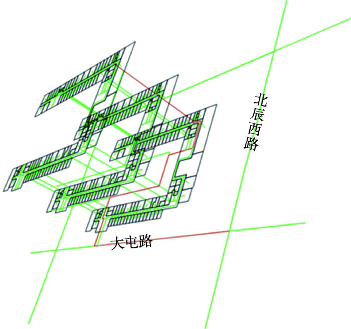
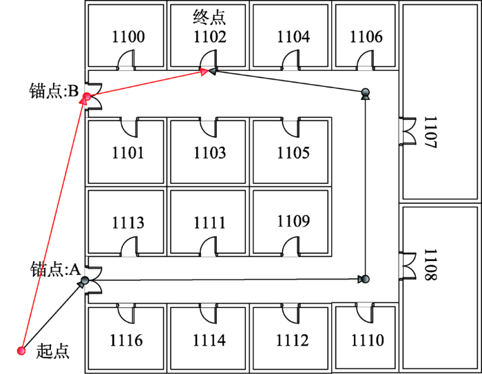
本文以中国科学院地理科学与资源研究所为研究区域的中心,结合周边实际路网数据构建实验区,如图7所示。研究室外某起点到室内某终点的最短路径,传统方式进行路径规划基于室内、外分开的2个导航路网,用Dijkstra算法计算最短路径时,首先求解出到起点最近的锚点,然后进行导航场景切换,计算该锚点到终点的最短路径,在2个导航路网下求解最优路径问题时存在局部最优解而非全局最优解的情况需要进行检查(如图8所示,起点到锚点A距离较近,但是经过锚点B的路径是全程最优的),需将经过不同锚点的路径距离进行排序,从而确定最短路径,该过程将会耗费大量的时间,但是基于本文提出的室内外一体化的导航路网进行路径规划时,不存在场景切换与全局最优的验证问题,因此会有更高的效率。下面将以具体的实验从效率方面来说明一体化导航路网的优势。
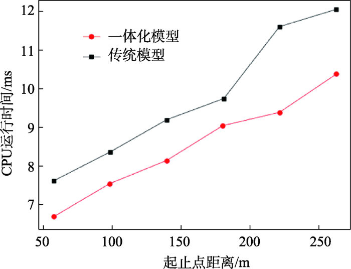
在试验区中基于传统室内外分开的导航路网和本文提出的一体化导航路网分别随机生成 10 000个起止点对,并针对每组起止点对计算最短路径。试验结果表明,一体化导航路网平均用时为7.890 ms;传统分场景计算的方式平均用时为 8.784 ms;整体上一体化模型比传统模型效率提升10.18%。根据规划路径长度及响应时间,分别计算70 m以下,70~120 m,120~170 m,170~220 m,220~270 m,270 m以上的最短路径平均距离及路径规划平均响应时间,统计图表如图9所示,对于每个路径长度区间,其平均效率分别提升12.36%,9.97%,11.59%,7.24%,19.24%,14.00%。
本文针对当前跨场景导航路网数据获取困难、导航效率低的问题,提出一种基于建筑物CAD数据自动构建室内外一体化导航路网的方法,并从效率上验证了该方法的有效性。本文提出的基于中轴变换算法的室内导航路网自动生成方法,相较人工数字化室内导航路网的方式可以快速、高效的自动生成室内导航路网;基于室内外一体化导航路网规划路径的方式相比传统的室内外分场景计算最优路径的方法可直接搜索整个导航路网,避免陷入单一室内或室外场景下的局部最优解而非全局最优的陷阱,提高了求解最优路径的效率和准确度。下一步将研究本方法对更复杂室内空间的有效性及改进方法,特别是像机场、商场这样具有广阔走廊和内部空间的室内场景。
The authors have declared that no competing interests exist.
| [1] |
顾及地标可视性的室内导航路径优化算法 [J].Indoor navigation path optimization algorithm considering the visibility of landmarks [J]. |
| [2] |
一种运动恢复结构和航位推算结合的室内行人视觉定位方法 [J].
商业和工业领域中,室内行人、车辆、机器人的位置信息正逐渐成为人们关注的热点,并随之产生了大量的室内定位技术和方法,如使用无线信号、地磁、超宽带和超声波等方式进行室内定位。然而,目前的这些室内定位方法大多需要额外辅助设备的支撑,增加了定位成本和硬件开销。视觉定位作为一种目前较为流行的定位方式,具有实施成本低、不依赖任何外界辅助设备等优势。其中,构建带有位置标签的图像数据库是视觉定位方法的关键环节,而传统的构建图像数据库方法人力开销大、时耗长。因此,本文提出一种运动恢复结构(SFM)和航位推算结合的视觉定位方法,能够快速构建图像位置数据库、大大降低人力开销。该方法主要包括2个阶段:离线阶段和在线阶段。离线阶段主要实现图像序列位置的自动标注,通过采集行走路线上的手机内置传感器信息和视频信息,提出一种多约束图像匹配方法用于视频图像的连续匹配,将匹配结果用于SFM方法,可以得到相邻图像间的运动角度,使用行人航位推算(PDR)方法标注图像序列的轨迹坐标。在线阶段使用提出的图像匹配方法计算查询图像与数据库影像间的匹配点数量,将匹配点最多的K个数据库影像位置坐标加权平均作为查询图像的定位结果。最后,分别在2种典型的室内环境下进行实验,结果表明本文方法在离线阶段位置标注的平均误差为0.58 m,在线阶段图像匹配定位的误差范围在0.2~1.4 m。
An indoor pedestrian positioning approach based on the integration of SFM and PDR [J].
商业和工业领域中,室内行人、车辆、机器人的位置信息正逐渐成为人们关注的热点,并随之产生了大量的室内定位技术和方法,如使用无线信号、地磁、超宽带和超声波等方式进行室内定位。然而,目前的这些室内定位方法大多需要额外辅助设备的支撑,增加了定位成本和硬件开销。视觉定位作为一种目前较为流行的定位方式,具有实施成本低、不依赖任何外界辅助设备等优势。其中,构建带有位置标签的图像数据库是视觉定位方法的关键环节,而传统的构建图像数据库方法人力开销大、时耗长。因此,本文提出一种运动恢复结构(SFM)和航位推算结合的视觉定位方法,能够快速构建图像位置数据库、大大降低人力开销。该方法主要包括2个阶段:离线阶段和在线阶段。离线阶段主要实现图像序列位置的自动标注,通过采集行走路线上的手机内置传感器信息和视频信息,提出一种多约束图像匹配方法用于视频图像的连续匹配,将匹配结果用于SFM方法,可以得到相邻图像间的运动角度,使用行人航位推算(PDR)方法标注图像序列的轨迹坐标。在线阶段使用提出的图像匹配方法计算查询图像与数据库影像间的匹配点数量,将匹配点最多的K个数据库影像位置坐标加权平均作为查询图像的定位结果。最后,分别在2种典型的室内环境下进行实验,结果表明本文方法在离线阶段位置标注的平均误差为0.58 m,在线阶段图像匹配定位的误差范围在0.2~1.4 m。
|
| [3] |
Handbook of virtual environments:Design, implementation, and applications [M]. |
| [4] |
HBase的面向语义单元的室内移动对象索引 [J].https://doi.org/10.3724/SP.J.1047.2017.00307 URL [本文引用: 1] 摘要
随着室内定位技术的广泛应用,传感器记录了大量室内移动对象的位置数据,而索引技术作为移动对象数据分析的基础工作也得到越来越多的研究.已有索引技术多是针对室外空间的移动对象,不能支持室内移动对象数据的三维立体性、轨迹的复杂性、随机性等特点,这些索引技术也仅仅关注了移动对象的位置信息,忽略了语义信息,不能有效地支持室内移动对象的管理和分析,并且当面对海量的移动对象数据时,这些架构在传统关系型数据库上的索引都存在性能瓶颈问题.因此,本文提出了面向语义单元的移动对象表达模型,利用语义单元将室内移动对象的位置语义化,设计了SCoII(Semantic Cell Oriented Indoor moving objects Index)索引结构对室内移动对象的历史数据进行索引,能够有效支持语义粒度上的时空范围查询、移动对象语义轨迹查询.索引基于HBase实现,能够适应大规模的并发更新与查询,具有良好的规模扩展性,规避了大数据给传统数据库带来的性能瓶颈问题,实验证明其具有良好的更新和查询性能.该索引的实现方便了基于语义的室内移动对象分析和数据挖掘工作,为今后的分析工作奠定了基础.
Semantic cell oriented indoor moving objects index based on HBase [J].https://doi.org/10.3724/SP.J.1047.2017.00307 URL [本文引用: 1] 摘要
随着室内定位技术的广泛应用,传感器记录了大量室内移动对象的位置数据,而索引技术作为移动对象数据分析的基础工作也得到越来越多的研究.已有索引技术多是针对室外空间的移动对象,不能支持室内移动对象数据的三维立体性、轨迹的复杂性、随机性等特点,这些索引技术也仅仅关注了移动对象的位置信息,忽略了语义信息,不能有效地支持室内移动对象的管理和分析,并且当面对海量的移动对象数据时,这些架构在传统关系型数据库上的索引都存在性能瓶颈问题.因此,本文提出了面向语义单元的移动对象表达模型,利用语义单元将室内移动对象的位置语义化,设计了SCoII(Semantic Cell Oriented Indoor moving objects Index)索引结构对室内移动对象的历史数据进行索引,能够有效支持语义粒度上的时空范围查询、移动对象语义轨迹查询.索引基于HBase实现,能够适应大规模的并发更新与查询,具有良好的规模扩展性,规避了大数据给传统数据库带来的性能瓶颈问题,实验证明其具有良好的更新和查询性能.该索引的实现方便了基于语义的室内移动对象分析和数据挖掘工作,为今后的分析工作奠定了基础.
|
| [5] |
|
| [6] |
An algebraic approach to image schemas for geographic space [ |
| [7] |
The informatics of indoor and outdoor space: A research agenda [C]. |
| [8] |
Modeling indoor space [C]. |
| [9] |
|
| [10] |
Applying hierarchical graphs to pedestrian indoor navigation [C]. |
| [11] |
A Spatial Access-Oriented Implementation of a 3-D GIS Topological Data Model for Urban Entities [J].https://doi.org/10.1023/B:GEIN.0000034820.93914.d0 URL [本文引用: 2] 摘要
3-D analysis in GIS is still one of the most challenging topics for research. With the goal being to model possible movement within the built environment, this paper, therefore, proposes a new approach to handling connectivity relationships among 3-D objects in urban environments in order to implement spatial access analyses in 3-D space. To achieve this goal, this paper introduces a 3-D network data model called the geometric network model (GNM), which has been developed by transforming the combinatorial data model (CDM), representing a connectivity relationship among 3-D objects using a dual graph. For the transformation, this paper presents (1) an O ( n 2 ) algorithm for computing a straight medial axis transformation (MAT), (2) the processes for transforming phenomena from 3-D CDM to 3-D GNM, and (3) spatial access algorithms for the 3-D geometric network based upon the Dijkstra algorithm. Using the reconstructed geometric network generated from the transformations, spatial queries based upon the complex connectivity relationships between 3-D urban entities are implemented using Dijkstra algorithm. Finally, the paper presents the results of an experimental implementation of a 3-D network data model (GNM) using GIS data of an area in downtown Columbus, Ohio.
|
| [12] |
A combinatorial data model for representing topological relations among 3D geographical features in micro-spatial environments [J].https://doi.org/10.1080/13658810500399043 URL [本文引用: 1] 摘要
This research is motivated by the need for 3D GIS data models that allow for 3D spatial query, analysis and visualization of the subunits and internal network structure of ‘micro‐spatial environments’ (the 3D spatial structure within buildings). It explores a new way of representing the topological relationships among 3D geographical features such as buildings and their internal partitions or subunits. The 3D topological data model is called the combinatorial data model (CDM). It is a logical data model that simplifies and abstracts the complex topological relationships among 3D features through a hierarchical network structure called the node‐relation structure (NRS). This logical network structure is abstracted by using the property of Poincaré duality. It is modelled and presented in the paper using graph‐theoretic formalisms. The model was implemented with real data for evaluating its effectiveness for performing 3D spatial queries and visualization.
|
| [13] |
|
| [14] |
|
| [15] |
Biquasiles and dual graph diagrams [J].https://doi.org/10.1142/S0218216517500481 URL [本文引用: 1] 摘要
We introduce \textit{dual graph diagrams} representing oriented knots and links. We use these combinatorial structures to define corresponding algebraic structures we call \textit{biquasiles} whose axioms are motivated by dual graph Reidemeister moves, generalizing the Dehn presentation of the knot group analogously to the way quandles and biquandles generalize the Wirtinger presentation. We use these structures to define invariants of oriented knots and links. In particular, we identify an example of a finite biquasile whose counting invariant distinguishes the chiral knot $9_{32}$ from its mirror image, demonstrating that biquasile counting invariants are distinct from biquandle counting invariants.
|
| [16] |
A Three-Dimensional Navigable Data Model to Support Emergency Response in Microspatial Built-Environments [J].https://doi.org/10.1111/j.1467-8306.2007.00561.x URL [本文引用: 1] 摘要
Since the 11 September 2001 attacks in the United States and the 7 July 2005 London bombings, geospatial researchers have attempted to utilize GIScience technologies in response to disasters occurring in the microspace of multilevel structures (such as the interior of buildings) in urban areas. Such applications require 3D geographic information systems (GIS) functionalities to represent the three-dimensional structures of urban environments and to conduct 3D GIS-based spatial analyses. These requirements motivate this study to represent the complex internal structure of buildings at a three-dimensional subunit level so as to analyze human behavior in an emergency situation. This article discusses the development of a 3D Navigable Data Model (3D NDM) based on the 3D Geometric Network Data Model and representing pedestrian access within buildings or urban built-environments, which can be modeled as a network of walkway sections and connections. Additionally, this article discusses the design of a geospatial database created to manage the physical and environmental factors of disaster sites that are essential for emergency response. To improve planning and facilitate rescue operations in a decision support system, this article presents (1) a 3D geo-coding method to locate rescue personnel and disaster sites within the reference data (a network representation of a building), (2) a 3D map matching method to define the correlation between the location of bottlenecks or disaster sites and the nearest location on the 3D NDM, which represents the internal structure of the built-environment as a network representation, and (3) an indoor navigation model, based on the Dijkstra algorithm, to identify optimal routes within a multilevel structure by measuring relative pedestrian accessibility and to provide navigation guidance for rescue personnel. Lastly, this article presents the results of an experimental implementation of the 3D NDM using GIS data for a section of the University of North Carolina at Charlotte campus.
|
| [17] |
|
| [18] |
Generation and use of sparse navigation graphs for microscopic pedestrian simulation models [M]. |
| [19] |
全息位置地图概念内涵及其关键技术初探 [J].https://doi.org/10.13203/j.whugis20140462 URL [本文引用: 1] 摘要
This paper analysis the limitations and challenges of the traditional digital map in ubiquitous information and big data era.We extend the original concept of a Parrlocation Information Map(PLIM) that in the ubiquitous network environment.PLIM dynamically associates mutli-temporal,multi-thematic,multi-hierarchical,multi-granular information about objects or events based on location,and provides a personalized location and location-related information service platform.Also,we describe the structure and characteristics of a new PLIM and demonstrate the key technologies in three aspects,including ubiquitous information acquisition,semantic location correlation,and establishment of a multi-dimensional visualization map.
Holographic location map discussion on the connotation and key technologies [J].https://doi.org/10.13203/j.whugis20140462 URL [本文引用: 1] 摘要
This paper analysis the limitations and challenges of the traditional digital map in ubiquitous information and big data era.We extend the original concept of a Parrlocation Information Map(PLIM) that in the ubiquitous network environment.PLIM dynamically associates mutli-temporal,multi-thematic,multi-hierarchical,multi-granular information about objects or events based on location,and provides a personalized location and location-related information service platform.Also,we describe the structure and characteristics of a new PLIM and demonstrate the key technologies in three aspects,including ubiquitous information acquisition,semantic location correlation,and establishment of a multi-dimensional visualization map.
|
| [20] |
A combinatorial representation of polyhedral surfaces [J].
Search all the public and authenticated articles in CiteULike. Include unauthenticated resultstoo (may include "spam") Enter a search phrase. You can also specify a CiteULike article id(123456),. a DOI (doi:10.1234/12345678). or a PubMed ID (pmid:12345678).
|
| [21] |
|
| [22] |
优化的离散λ-中轴骨架提取算法 [J].
离散λ-中轴(DLMA)是一种快速、健壮的中轴变换算法,选择合适的参数λ可以提取物体较为精准的单像素骨架.针对DLMA算法的缺点,提出一种融合欧氏距离变换局部极大值点思想和背景点空间思想的DLMA优化算法.该算法将DLMA算法分成2步,先使用一个小λ阈值获得骨架的粗提取结果,计算过程中将其N4邻域简化为N2邻域;然后在粗提取的结果下设计骨架生长阈值自动调整策略,使其对宽度变化具有足够的适应性.实验结果表明,与原DLMA算法相比,文中提出的优化算法不仅具有更快的计算速度,鲁棒性和自适应能力均有显著提高.
Skeleton extraction algorithm for discrete optimization of Lambda-axis [J].
离散λ-中轴(DLMA)是一种快速、健壮的中轴变换算法,选择合适的参数λ可以提取物体较为精准的单像素骨架.针对DLMA算法的缺点,提出一种融合欧氏距离变换局部极大值点思想和背景点空间思想的DLMA优化算法.该算法将DLMA算法分成2步,先使用一个小λ阈值获得骨架的粗提取结果,计算过程中将其N4邻域简化为N2邻域;然后在粗提取的结果下设计骨架生长阈值自动调整策略,使其对宽度变化具有足够的适应性.实验结果表明,与原DLMA算法相比,文中提出的优化算法不仅具有更快的计算速度,鲁棒性和自适应能力均有显著提高.
|
| [23] |
Medial axis and singularities [J].https://doi.org/10.1007/s12220-017-9763-x URL [本文引用: 1] |
| [24] |
Medial axis transformation of a planar shape [J].https://doi.org/10.1109/TPAMI.1982.4767267 URL PMID: 21869050 [本文引用: 1] 摘要
Abstract The medial axis transformation is a means first proposed by Blum to describe a shape. In this paper we present a 0(n log n) algorithm for computing the medial axis of a planar shape represented by an n-edge simple polygon. The algorithm is an improvement over most previously known results interms of both efficiency and exactness and has been implemented in Fortran. Some computer-plotted output of the program are also shown in the paper.
|

/
| 〈 |
|
〉 |